Product Description
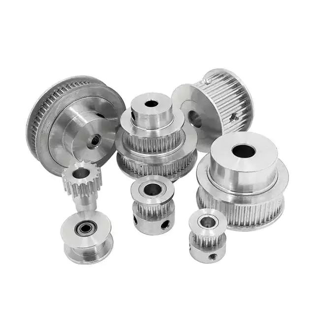
Motorcycle Parts CNC Processing Manufacturing China Automobile Square Nut Machining Sleeve Spacer Pulley
Product Information
Product Information:
| 1 | Business Type: | Custom CNC Milling Service (3-axis, 4-axis, 5-axis) Custom CNC Turning Services EDM Wire-EDM |
| 2 | Standard: | JIS, ANSI |
| 3 | Products Range: | Automobile parts,wind power generation equipment accessories,wind power generation equipment accessories, ER fluid, medical apparatus and instruments, standardization of custom, moto parts, machinery parts, lighting components, hardware accessories, electric motor products, etc |
| Agricultural machinery, electrical appliances, furniture hardware | ||
| 4 | Materials: | 1.Stainless Steel: SS201, SS303, SS304, SS316 etc. |
| 2.Carbon Steel: AISI 1045, 9SMnPb28 etc | ||
| 3.Brass: C36000 (C26800), C37700 (HPb59), C38500(HPb58), C27200(CuZn37), C28000(CuZn40) etc. | ||
| 4.Bronze:C51000, C52100, C54400, etc. | ||
| 5.Iron:Grey iron and ductile iron | ||
| 6.Aluminum:6061, 6063,7075,5052 etc. | ||
| 7.Magnesium Alloy: AZ31, AZ61, AZ91 | ||
| 8.Plastic: PEEK, POM, NYLON, TEFLON, ABS…etc | ||
| 9.Titanium: TC4 | ||
| 5 | Machining: | Turning, Milling, Drilling, Grinding, Cleaning, |
| 6 | Main equipments | CNC lathe, CNC milling, Stamping machine, |
| Automatic lathe, Grinder, Tapping | ||
| Drilling machine…etc | ||
| 7 | Measuring & Testing equipments | CMM, Profile Projector, Rockwell Hardness Tester, CZPT Hardness Tester, Roughness Tester, Micrometers, height gauge, Calipers… etc. |
| 8 | Accuracy: | Accuracy Of Machining:+/-0.005mm |
| Accuracy Of Grinding:+/-0.005mm | ||
| Surface Roughness:Ra0.8 | ||
| Parallelism:+/-0.005mm | ||
| Verticality:+/-0.005mm | ||
| Concentricity:0.003mm | ||
| 9 | Surface Treatment: | Polishing, Deburring, Chrome Plating, Ni Plated, Zinc plated, Silver platinng |
| Anodizing various colors, Carburizing Nitriding, Heat Treatment, etc… | ||
| 10 | MOQ | 1 ~10000pcs. |
| 11 | DRW Format: | DWG, PDF, IGS, STEP, SLDPRT, SLDDRW, PRT, DRW, DXF, X_T, etc… |
| 12 | QC System: | 100% Inspection before shipment |
| 13 | Certificate | ISO9001: 2015, SGS Factory Audit |
| 14 | Payment Term: | 30% T/T + 70% T/T, Western Union, PayPal, L/C |
| 15 | Trade Terms: | FOB, CIF, L/C |
| 16 | Lead time: | 7~45 days after confirming |
| 17 | Sample Lead Time: | 3-7 Working Days |
| 18 | Transport Package: | Foam/wooden box, Anti-rust paper, Small box and carton, Pallets… etc. |
| 19 | Origin: | China |
| 20 | Our Advantages: | Reliable Quality |
| Competitive Price | ||
| High precision, high quality, high accurancy | ||
| Continuous Improvement | ||
| Defect-Free Products | ||
| On-Time Delivery | ||
| Customer Satisfaction | ||
| Excellent After-Sales Service |
Production Process
Company Profile
JieChen Precision Manufacturing Co., Ltd is a professional precision machining parts manufacturer. We specialize in precision machining parts processing, precision tooling, jig & fixture, automation equipment design and manufacturing.
Since its establishment in 2012, the company has been developing at a high speed. Now with big space workshop and many advanced production equipments and precision measure equipments.
Customers distributes to Europe and the United States, Japan, Germany, England and the mainland international CZPT enterprises, the company has been focusing on human resources development and training, provide the broad development space for the employees.
Products covered the defense, aerospace, electronics, medical, semi-conductor, automation and other industries. With parts variety, high precision, large, medium batch processing parts, product precision reached 0.002 mm, in compliance with ISO, ASME, DIN, JIS quality systems.
JieChen Precision – Your Right Choice!
Quality Control Standards
To consistently exceed customer expectations, qua lity control and assurance is achieved through
Comprehensive written procedures and policies
Fully equipped inspection department
Detailed records of incoming raw materia
Consistent calibration and labeling of inspection tools
Analysis of root cause of non-conformances.
Staff members being strongly encouraged to sugqest improvements in methods, materials and suppliers
Certifications
Application instructions
Packaging & Shipping
FAQ
Q: Are you trading company or manufacturer ?
A: We are direct factory with experienced engineers and employees as well as well-organized workshop.
Q: How long is your delivery time?
A: Generally it is 5-10 days if the goods are in stock. or it is 15-20 days if the goods are not in stock, it is according to quantity.
Q: Do you provide samples ? is it free or extra ?
A: Yes, the sample fee depends on the product geometry, and the fee will be returned to your bulk order.
Q: How long can I get the sample?
A: Depends on your part geometry, normally within 3-7 days.
Q: How long is your delivery time?
A: Sample 3-7days; Mass production order 7-45 days depends on quantity and part complexity.
Q: What is your terms of payment ?
A: Payment=1000USD, 30% T/T in advance ,balance before shippment.
Q: What’s kinds of information you need for a quote?
A: Kindly please provide the product 2D drawing with PDF or DWG format and 3D drawings with STEP or IGS or X_T format, and other requirements like: surface treatment, quantity…etc.
Q: What is your standard PO procurement process flow?
A: Prototyping —-> FA approval —-> Quality Control Plan —> Manufacturing Process Instruction —> Batch Production —> Inspection —> Shipping
Q: What shall we do if we do not have drawings?
A. Please send your sample to our factory, then we can copy or provide you better solutions. Please send us pictures or drafts with dimensions (Length, Height, Width), CAD or 3D file will be made for you if placed order.
Q: Will my drawings be safe after sending to you?
A: Yes, we can CZPT the NDA before got your drawing and will not release to the third party without your permission
Q: Is it possible to know how are my products going on without visiting your company?
A: We will offer a detailed production schedule and send weekly reports with digital pictures and videos which
show the machining progress
Q: How to enjoy the OEM services?
A: Usually, base on your design drawings or original samples, we give some technical proposals and a quotation
to you, after your agreement, we produce for you.
If you have another question, pls feel free to contact us
| Condition: | New |
|---|---|
| Certification: | CE, RoHS, GS, ISO9001 |
| Standard: | DIN, ASTM, GOST, GB, JIS, ANSI, BS |
| Customized: | Customized |
| Material: | Magnesium Alloy |
| Application: | Metal Recycling Machine, Metal Cutting Machine, Metal Straightening Machinery, Metal Spinning Machinery, Metal Processing Machinery Parts, Metal forging Machinery, Metal Engraving Machinery, Metal Drawing Machinery, Metal Coating Machinery, Metal Casting Machinery, Medical Spare Part, Telecommunication Part |
| Samples: |
US$ 100/Piece
1 Piece(Min.Order) | |
|---|
| Customization: |
Available
| Customized Request |
|---|
Calculate the ideal mechanical advantage of pulleys
The basic equations for pulleys can be found in this article. It will also cover the different types of pulleys, the ideal mechanical advantages of pulleys, and some common uses of pulley systems. Read on to learn more! After all, a pulley is a simple mechanical device that changes the direction of a force. Learn more about pulleys and their common uses in engineering.
pulley basic equation
Pulleys work the same way as gravity, so they should withstand similar forces. Newton’s laws of motion can be used to calculate the forces in a pulley system. The second law of motion applies to forces and accelerations. Similar to this is Newton’s third law, which states that the directions of forces are equal and opposite. The fourth law dictates the direction of force. The Fifth Law states that tension is in equilibrium with gravity.
A pulley is a simple mechanism that transmits force by changing direction. They are generally considered to have negligible mass and friction, but this is only an approximation. Pulleys have different uses, from sailboats to farms and large construction cranes. In fact, they are the most versatile mechanisms in any system. Some of their most common applications and equations are listed below.
For example, consider two masses m. Those of mass m will be connected by pulleys. The static friction coefficient of the left stop is ms1, and the static friction coefficient of the right stop is ms2. A no-slip equation will contain multiple inequalities. If the two blocks are considered to be connected by a pulley, the coefficient of kinetic friction is mk. In other words, the weight of each block carries the same mass, but in the opposite direction.
Types of pulleys
A pulley is a device used to pull and push objects. Pulley systems are ropes, cables, belts or chains. The “drive pulley” is attached to the shaft and moves the driven pulley. They are available in a variety of sizes, and the larger they are, the higher the speed of power transmission. Alternatively, use small pulleys for smaller applications.
Two-wheel pulleys have two mechanical advantages. The greater the mechanical advantage, the less force is required to move the object. More wheels lift more weight, but smaller pulleys require less force. In a two-wheel pulley system, the rope is wound around two axles and a fixed surface. As you pull on the rope, the shafts above slowly come together.
Compound pulleys have two or more rope segments that are pulled up on the load. The mechanical advantage of compound pulleys depends on the number of rope segments and how they are arranged. This type of pulley can increase the force by changing the direction of the rope segment. There are two main types of pulleys. Composite pulleys are most commonly used in construction. The ideal mechanical advantage of pulleys is 2 or more.
Construction pulleys are a basic type. They are usually attached to wheel rails and can be lifted to great heights. Combinations of axes are also common. Construction pulleys can be raised to great heights to access materials or equipment. When used in construction, these pulleys are usually made of heavy materials such as wood or metal. They are secured with ropes or chains.
The ideal mechanical advantage of pulleys
The pulley system is a highly complex system with high mechanical advantages. Use a single pulley system to reduce the force required to lift an object by cutting it in half. The mechanical advantage increases as you add more pulleys, such as six or seven. To calculate the mechanical advantage of a pulley system, you need to count the number of rope segments between the pulleys. If the free end of the rope is facing down, don’t count it. If it’s facing up, count. Once you have your number, add it up.
The required mechanical advantage of a pulley is the number of rope segments it has to pull the load. The more rope segments, the lower the force. Therefore, the more rope segments the pulley has, the lower the force. If the rope segments are four, then the ideal mechanical advantage is four. In this case, the composite pulley quadrupled the load force.
The ideal mechanical advantage of a pulley system is the sum of the mechanical force and the force required to lift the load at its output. Typically, a single pulley system uses two ropes, and the mechanical force required to lift the load is multiplied by the two ropes. For a multi-pulley system, the number of ropes will vary, but the total energy requirement will remain the same. The friction between the rope and pulley increases the force and energy required to lift the load, so the mechanical advantage diminishes over time.
Common uses of pulley systems
A pulley system is a simple mechanical device typically used to lift heavy objects. It consists of a rotating wheel attached to a fixed shaft and a rope attached to it. When the wheel moves, the force applied by the operator is multiplied by the speed of the pulley, and the force is multiplied by the weight of the object being lifted. Common uses for pulley systems include pulling, lifting, and moving heavy objects.
The oil and petroleum industries use pulley systems in a variety of applications. Most commonly, pulleys are used in drilling operations and they are installed on top of the rig to guide the cable. The cable itself is attached to two pulleys suspended in the derrick, where they provide mechanical energy to the cable. Using a pulley system in this application provides the force needed to move the cable safely and smoothly.
The main advantage of the pulley system is that it minimizes the force required to lift an object. The force used to lift the object is multiplied by the desired mechanical advantage. The more rope segments, the lower the force required. On the other hand, a compound pulley system can have many segments. Therefore, a compound pulley system can increase the force a worker can exert on an object.
Safety Precautions to Take When Working on Pulley Systems
There are many safety precautions that should be observed when working on a pulley system. The first is to wear proper protective gear. This includes hard hats that protect you from falling objects. Also, gloves may be required. You should limit the amount of movement in the penalty area, and you should also keep the area free of unnecessary people and objects. Also, remember to wear a hard hat when working on the pulley system.
Another important safety precaution when working on a pulley system is to check the Safe Working Load (SWL) of the pulley before attaching anything. This will help you understand the maximum weight the pulley can hold. Also, consider the angle and height of the pulley system. Always use safety anchors and always remember to wear a hat when working on a pulley system.
Safe use of chain hoists requires training and experience. It is important to read the manufacturer’s manual and follow all safety precautions. If you’re not sure, you can actually inspect the hoist and look for signs of damage or tampering. Look for certifications for sprocket sets and other lifting accessories. Look for the Safe Working Load (SWL) marking on the chain hoist.
Example of a pulley system
Pulley systems are often used to lift items. It allows you to reduce the effort to lift and move the load by applying force in one direction. Pulley systems can be built and modeled to fit any type of project. This resource focuses on pulley systems and is designed to support the new GCSEs in Engineering, Design and Technology. There are also many examples of pulley systems suitable for various applications.
In the study, participants who read easy text took longer to manipulate the pulley system than those who read challenging text. In general, this suggests that participants with prior scientific experience used their cognitive abilities more effectively. Additionally, students who read simple texts spent less time planning the pulley system and more time on other tasks. However, the study did show that the time required to plan the pulley system was similar between the two groups.
In everyday life, pulley systems are used to lift various objects. Flagpoles are one of many pulley systems used to raise and lower flagpoles. They can also be used to raise and lower garage doors. Likewise, rock climbers use pulleys to help them ascend and descend. The pulley system can also be used to extend the ladder.


editor by CX
2023-07-12