Product Description
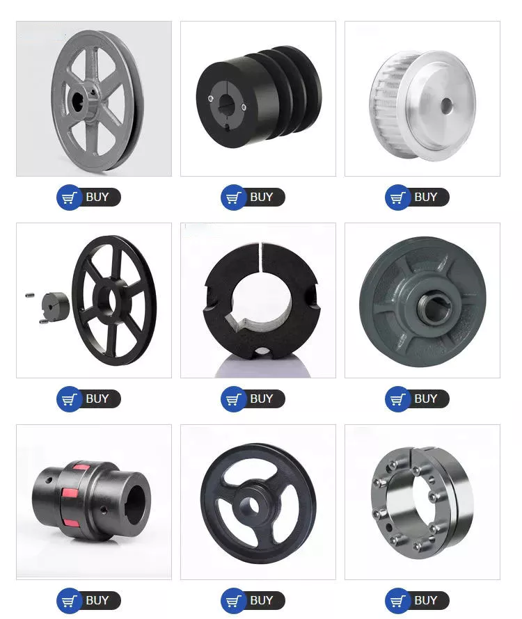
CHINAMFG Machinery offers a wide range of high quality Timing Belt Pulleys and Toothed Bars / Timing Bars. Standard and non-standard pulleys according to drawings are available.
Types of material:
1. AlCuMgPb 6061 6082 Aluminum Timing Pulley
2. C45E 1045 S45C Carbon Steel Timing Pulley
3. GG25 HT250 Cast Iron Timing Pulley
4. SUS303 SUS304 AISI431 Stainless Steel Timing Pulley
5. Other material on demand, such as cooper, bronze and plastic
Types of surface treatment
1. Anodized surface -Aluminum Pulleys
2. Hard anodized surface — Aluminum Pulleys
3. Black Oxidized surface — Steel Pulleys
4. Zinc plated surface — Steel Pulleys
5. Chromate surface — Steel Pulleys; Cast Iron Pulleys
6. Nickel plated surface –Steel Pulleys; Cast Iron Pulleys
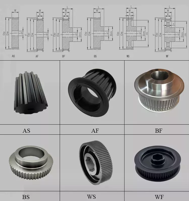
Types of teeth profile
| Teeth Profile | Pitch |
| HTD | 3M,5M,8M,14M,20M |
| AT | AT5,AT10,AT20 |
| T | T2.5,T5,T10 |
| MXL | 0.08″(2.032MM) |
| XL | 1/5″(5.08MM) |
| L | 3/8″(9.525MM) |
| H | 1/2″(12.7MM) |
| XH | 7/8″(22.225MM) |
| XXH | 1 1/4″(31.75MM) |
| STS STPD | S2M,S3M,S4.5M,S5M,S8M,S14M |
| RPP | RPP5M,RPP8M,RPP14M,RPP20M |
| PGGT | PGGT 2GT, 3GT and 5GT |
| PCGT | GT8M,GT14M |
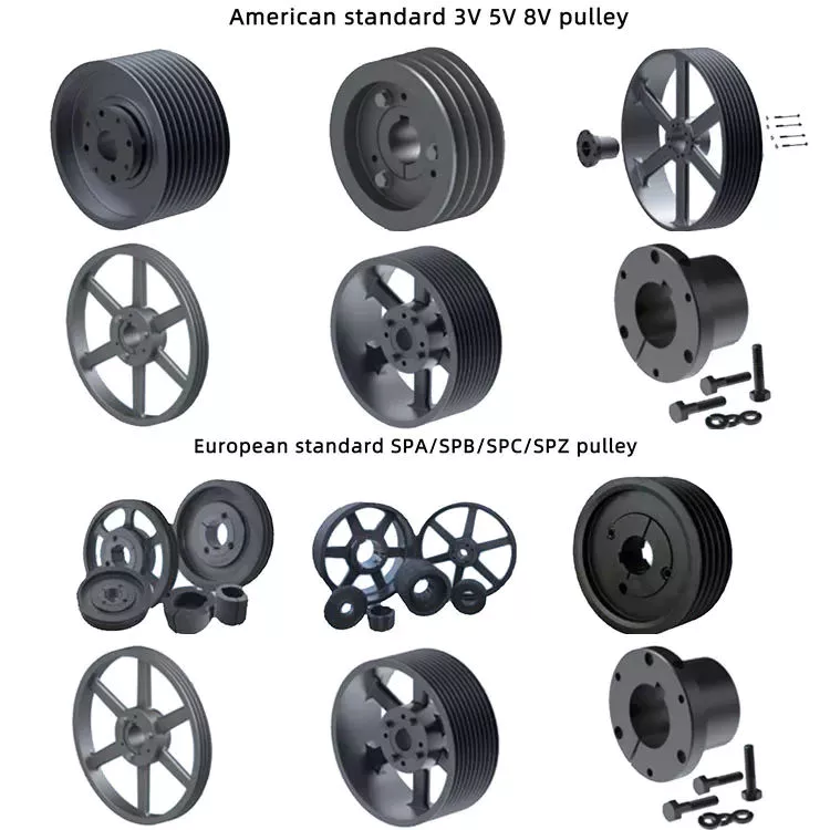
Types of pitches and sizes
Imperial Inch Timing Belt Pulley,
1. Pilot Bore MXL571 for 6.35mm timing belt; teeth number from 16 to 72;
2. Pilot Bore XL037 for 9.53mm timing belt; teeth number from 10 to 72;
3. Pilot Bore, Taper Bore L050 for 12.7mm timing belt; teeth number from 10 to 120;
4. Pilot Bore, Taper Bore L075 for 19.05mm timing belt; teeth number from 10 to 120;
5. Pilot Bore, Taper Bore L100 for 25.4mm timing belt; teeth number from 10 to 120;
6. Pilot Bore, Taper Bore H075 for 19.05mm timing belt; teeth number from 14 to 50;
7. Pilot Bore, Taper Bore H100 for 25.4mm timing belt; teeth number from 14 to 156;
8. Pilot Bore, Taper Bore H150 for 38.1mm timing belt; teeth number from 14 to 156;
9. Pilot Bore, Taper Bore H200 for 50.8mm timing belt; teeth number from 14 to 156;
10. Pilot Bore, Taper Bore H300 for 76.2mm timing belt; teeth number from 14 to 156;
11. Taper Bore XH200 for 50.8mm timing belt; teeth number from 18 to 120;
12. Taper Bore XH300 for 76.2mm timing belt; teeth number from 18 to 120;
13. Taper Bore XH400 for 101.6mm timing belt; teeth number from 18 to 120;
Metric Timing Belt Pulley T and AT
1. Pilot Bore T2.5-16 for 6mm timing belt; teeth number from 12 to 60;
2. Pilot Bore T5-21 for 10mm timing belt; teeth number from 10 to 60;
3. Pilot Bore T5-27 for 16mm timing belt; teeth number from 10 to 60;
4. Pilot Bore T5-36 for 25mm timing belt; teeth number from 10 to 60;
5. Pilot Bore T10-31 for 16mm timing belt; teeth number from 12 to 60;
6. Pilot Bore T10-40 for 25mm timing belt; teeth number from 12 to 60;
7. Pilot Bore T10-47 for 32mm timing belt; teeth number from 18 to 60;
8. Pilot Bore T10-66 for 50mm timing belt; teeth number from 18 to 60;
9. Pilot Bore AT5-21 for 10mm timing belt; teeth number from 12 to 60;
10. Pilot Bore AT5-27 for 16mm timing belt; teeth number from 12 to 60;
11. Pilot Bore AT5-36 for 25mm timing belt; teeth number from 12 to 60;
12. Pilot Bore AT10-31 for 16mm timing belt; teeth number from 15 to 60;
13. Pilot Bore AT10-40 for 25mm timing belt; teeth number from 15 to 60;
14. Pilot Bore AT10-47 for 32mm timing belt; teeth number from 18 to 60;
15. Pilot Bore AT10-66 for 50mm timing belt; teeth number from 18 to 60;
Metric Timing Belt Pulley HTD3M, 5M, 8M, 14M
1. HTD3M-06; 3M-09; 3M-15; teeth number from 10 to 72;
2. HTD5M-09; 5M-15; 5M-25; teeth number from 12 to 72;
3. HTD8M-20; 8M-30; 8M-50; 8M-85 teeth number from 22 to 192;
4. HTD14M-40; 14M-55; 14M-85; 14M-115; 14M-170; teeth number from 28-216;
5. Taper Bore HTD5M-15; 8M-20; 8M-30; 8M-50; 8M-85; 14M-40; 14M-55; 14M-85;
14M-115; 14M-170
Metric Timing Belt Pulleys for Poly Chain GT2 Belts
1. PCGT8M-12; PCGT8M-21; PCGT8M-36; PCGT8M-62;
2. PCGT14M-20; PCGT14M-37; PCGT14M-68; PCGT14M-90; PCGT14M-125;
Power Grip CHINAMFG Tooth/ PGGT 2GT, 3GT and 5GT
1. 2GT-06, 2GT-09 for timing belt width 6mm and 9mm
2. 3GT-09, 3GT-15 for timing belt width 9mm and 15mm
3. 5GT-15, 5GT-25 for timing belt width 15mm and 25mm
OMEGA RPP HTD Timing Pulleys
1. RPP3M-06; 3M-09; 3M-15; teeth number from 10 to 72;
2. RPP5M-09; 5M-15; 5M-25; teeth number from 12 to 72;
3. RPP8M-20; 8M-30; 8M-50; 8M-85 teeth number from 22 to 192;
4. RPP14M-40; 14M-55; 14M-85; 14M-115; 14M-170; teeth number from 28-216;
5. Taper Bore RPP5M-15; 8M-20; 8M-30; 8M-50; 8M-85; 14M-40; 14M-55; 14M-85;
14M-115; 14M-170 .
Ubet Machinery is also competetive on these power transmission components.
/* January 22, 2571 19:08:37 */!function(){function s(e,r){var a,o={};try{e&&e.split(“,”).forEach(function(e,t){e&&(a=e.match(/(.*?):(.*)$/))&&1
| Certification: | ISO |
|---|---|
| Pulley Sizes: | Timing |
| Manufacturing Process: | Sawing |
| Samples: |
US$ 3/Piece
1 Piece(Min.Order) | Order Sample Normally sample order can be ready in 15 days
|
|---|
| Customization: |
Available
| Customized Request |
|---|
.shipping-cost-tm .tm-status-off{background: none;padding:0;color: #1470cc}
|
Shipping Cost:
Estimated freight per unit. |
about shipping cost and estimated delivery time. |
|---|
| Payment Method: |
|
|---|---|
|
Initial Payment Full Payment |
| Currency: | US$ |
|---|
| Return&refunds: | You can apply for a refund up to 30 days after receipt of the products. |
|---|
How does the diameter of a pulley affect its mechanical advantage?
The diameter of a pulley plays a significant role in determining its mechanical advantage. Mechanical advantage refers to the ratio of the output force or load to the input force or effort applied to the pulley system. Here’s how the diameter of a pulley affects its mechanical advantage:
1. Larger Diameter: When the diameter of a pulley increases, the mechanical advantage also increases. A larger diameter means that the circumference of the pulley is greater, allowing a longer length of rope or belt to be wrapped around it. As a result, a larger pulley requires less effort force to lift a given load. This is because the load is distributed over a greater length of rope or belt, reducing the force required to overcome the load.
2. Smaller Diameter: Conversely, when the diameter of a pulley decreases, the mechanical advantage decreases. A smaller diameter means that the circumference of the pulley is reduced, resulting in a shorter length of rope or belt wrapped around it. As a result, a smaller pulley requires more effort force to lift a given load. This is because the load is concentrated over a shorter length of rope or belt, requiring a greater force to overcome the load.
It’s important to note that while a larger diameter pulley offers a greater mechanical advantage in terms of reducing the effort force required, it also results in a slower speed of the load being lifted. This is because the longer length of rope or belt requires more input distance to achieve a given output distance. On the other hand, a smaller diameter pulley offers a lower mechanical advantage but allows for a faster speed of the load being lifted.
The mechanical advantage of a pulley system can be calculated using the formula:
Mechanical Advantage = Load / Effort
Where “Load” refers to the weight or force being lifted and “Effort” refers to the force applied to the pulley system. By adjusting the diameter of the pulley, the mechanical advantage can be optimized to suit the specific requirements of the application, balancing the effort force and speed of the load being lifted.
Can pulleys be part of renewable energy systems like wind turbines?
Yes, pulleys can indeed be part of renewable energy systems like wind turbines. While wind turbines primarily rely on the force of the wind to generate electricity, pulleys are used in various components to facilitate the efficient conversion of wind energy into electrical power. Here’s how pulleys can be incorporated into wind turbines:
1. Rotor and Blade Pitch Control:
Pulleys are utilized in the rotor and blade pitch control mechanism of wind turbines. The rotor consists of multiple blades that capture the wind’s energy and convert it into rotational motion. To optimize the turbine’s performance, the pitch angle of the blades needs to be adjusted based on wind conditions. Pulleys and cables are employed to control the pitch angle, allowing the blades to be positioned at the optimal angle to maximize power output. The pulley system enables precise and synchronized blade adjustment, ensuring efficient wind capture.
2. Generator System:
In wind turbines, pulleys are also utilized in the generator system. The rotational motion of the turbine’s rotor is transferred to the generator through a series of mechanical components, including pulleys and belts or gears. The pulleys help to increase or decrease the rotational speed and torque as needed to match the generator’s requirements. This mechanical advantage provided by the pulleys ensures that the generator operates at its optimal speed, enhancing the efficiency of electricity generation.
3. Lifting and Maintenance Systems:
Pulleys are often incorporated into the lifting and maintenance systems of wind turbines. Wind turbine components, such as the nacelle (housing the generator and other equipment) and the rotor blades, are large and heavy, requiring periodic inspection, repair, and replacement. Pulley systems are employed to lift and lower these components during maintenance activities. The pulleys, along with cables and hoists, allow for controlled and safe handling of the heavy parts, enabling efficient maintenance and minimizing downtime.
4. Access Systems:
In larger wind turbines, pulleys are utilized in access systems that provide safe and efficient access to various parts of the turbine, including the nacelle and the rotor blades. Climbing systems or platforms equipped with pulleys allow technicians to ascend or descend the turbine structure, providing easy access for inspection, maintenance, and repairs. Pulleys facilitate the movement of personnel and equipment, ensuring the safety and efficiency of wind turbine operations.
By incorporating pulleys into these different aspects of wind turbines, renewable energy systems can benefit from increased efficiency, improved maintenance procedures, and enhanced safety measures. Pulleys contribute to the overall performance and reliability of wind turbines, enabling the harnessing of wind energy for clean and sustainable electricity generation.
How do pulleys contribute to load distribution and lifting?
Pulleys play a crucial role in load distribution and lifting by providing mechanical advantage and distributing the load over multiple segments of rope or belt. Here’s how pulleys contribute to load distribution and lifting:
1. Mechanical Advantage: Pulleys provide mechanical advantage, which allows for the multiplication of the force applied to the rope or belt. When a force is applied to one end of the rope or belt, it creates tension that causes the pulley to rotate. As the pulley turns, the force is transmitted to the load attached to the other end of the rope or belt. By distributing the load over multiple pulleys, the force required to lift the load is reduced, making it easier to lift heavier objects.
2. Load Sharing: Pulleys enable load sharing among multiple segments of the rope or belt. In systems with multiple pulleys, such as block and tackle arrangements, the load is distributed over several segments of rope or belt. Each segment carries a fraction of the load, reducing the strain on each individual segment. Load sharing ensures that the load is evenly distributed, minimizing the risk of overload or failure in any single segment.
3. Directional Change: Pulleys allow for directional change in the force applied to the load. By redirecting the force along a different path, pulleys enable lifting and moving loads in various directions, including vertically, horizontally, or at an angle. This directional change is particularly useful in situations where the force needs to be applied from a different position or angle than the original force application.
4. Balance and Stability: Pulleys contribute to load distribution and lifting by providing balance and stability. The use of multiple pulleys in a system helps to distribute the load evenly, preventing excessive stress on any single point. This balanced distribution of the load enhances stability and reduces the risk of tipping or imbalance during lifting operations.
5. Control and Precision: Pulleys provide control and precision in load distribution and lifting. By adjusting the tension in the rope or belt, operators can achieve precise positioning and movement of the load. This level of control allows for accurate placement of heavy objects and ensures smooth and controlled lifting operations.
6. Increased Lifting Capacity: By leveraging mechanical advantage and load distribution, pulleys increase the lifting capacity. The mechanical advantage gained through the use of pulleys allows for the lifting of heavier loads with less effort. The load is distributed over multiple segments of rope or belt, reducing the force required to lift the load and enabling the lifting of objects that would otherwise be too heavy to lift manually.
Overall, pulleys contribute to load distribution and lifting by providing mechanical advantage, load sharing, directional change, balance and stability, control and precision, and increased lifting capacity. These contributions make pulleys an essential component in various lifting and load handling applications.


editor by CX
2024-03-10